How to Choose the Right Fiber Optic Transceivers for Your Network Infrastructure

Fiber optic transceivers play a crucial role in converting electrical signals to optical signals and vice versa, enabling data transmission over fiber optic cables. Choosing the right transceivers is essential for optimizing network performance, ensuring compatibility, and maximizing cost-effectiveness.

Experts at Fibermart will walk you through the key factors to consider when selecting fiber optic transceivers to meet your network requirements.

Fiber Optic Transceivers

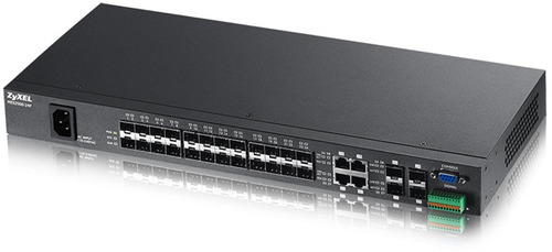
Fiber optic transceivers are modules that can transmit and receive data over fiber optic cables. They are commonly used in data centers, enterprise networks, telecommunications, and other high-bandwidth applications. Transceivers come in various form factors and types, each designed to meet specific needs in terms of distance, speed, and compatibility.

Recommended Read: How do Fiber optic transceivers work?

Common Types of Fiber Optic Transceivers

SFP (Small Form-factor Pluggable): Used for 1 Gbps Ethernet and Fibre Channel applications.

SFP+ (Enhanced Small Form-factor Pluggable): Supports data rates up to 10 Gbps.

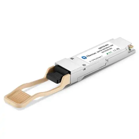
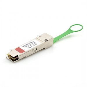
QSFP (Quad Small Form-factor Pluggable): Designed for 40 Gbps Ethernet.

QSFP28: Supports data rates up to 100 Gbps.

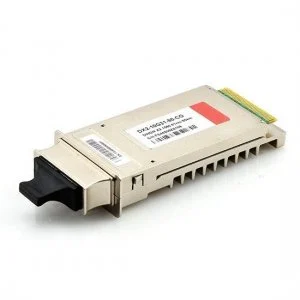
CFP (C Form-factor Pluggable): Used for 100 Gbps Ethernet applications.

Key Factors to Consider

Data Rate Requirements

The first step in choosing the right transceiver is understanding your network’s data rate requirements. The data rate refers to the speed at which data is transmitted, measured in Gbps (gigabits per second).

1 Gbps: Suitable for small to medium-sized businesses or less demanding applications.

10 Gbps: Common in enterprise networks and data centers for high-speed connectivity.

40 Gbps and 100 Gbps: Ideal for large-scale data centers and applications requiring ultra-high-speed connections.

Ensure that the transceiver you select matches the data rate requirements of your network equipment.

Explore More: How Will Fiber Optic Transceivers Evolve for Future Data Centers

Distance and Reach

The distance over which data needs to be transmitted is another crucial factor. Fiber optic transceivers are designed to support various transmission distances, from short-range to long-range.

Short-Range (SR): Typically used for distances up to 300 meters, ideal for intra-building connections.

Long-Range (LR): Suitable for distances up to 10 kilometers, used for inter-building connections.

Extended Range (ER) and Very Long Range (ZR): Can support distances up to 40 kilometers or more, used for metropolitan area networks (MAN) and wide area networks (WAN).

Choose a transceiver that can handle the required transmission distance without signal degradation.

Fiber Type

There are two main types of fiber optic cables: single-mode and multi-mode. The type of fiber you use will determine the appropriate transceiver.

Single-Mode Fiber (SMF): Used for long-distance transmission. Single-mode transceivers are typically more expensive but can handle higher bandwidth over longer distances.

Multi-Mode Fiber (MMF): Used for shorter distances due to higher attenuation and dispersion. Multi-mode transceivers are generally more cost-effective for shorter-reach applications.

Ensure compatibility between the transceiver and the type of fiber optic cable in your network.

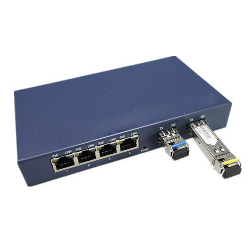
Compatibility with Network Equipment

Compatibility with existing network equipment is essential. Most transceivers are designed to be hot-swappable and fit into various network devices such as switches, routers, and servers. However, ensure that the transceiver you choose is compatible with your specific network hardware.

Brand Compatibility: Some manufacturers lock their equipment to work only with their transceivers. Verify compatibility with your equipment manufacturer.

Standards Compliance: Look for transceivers that comply with industry standards like IEEE and MSA (Multi-Source Agreement) to ensure interoperability.

Power Budget

The power budget is the amount of power available to ensure proper signal transmission over a given distance. It is the difference between the transmitter output power and the receiver sensitivity.

Ensure Adequate Power Budget: The power budget must be sufficient to compensate for any losses due to fiber attenuation, connector losses, and splices.

Environmental Conditions

Consider the environmental conditions where the transceivers will be deployed. Factors such as temperature, humidity, and exposure to elements can impact transceiver performance. If the transceivers will be used in harsh environments, choose industrial-grade models designed to withstand extreme conditions.

Future Scalability

Plan for future growth by selecting transceivers that can scale with your network needs. This includes considering higher data rates, longer distances, and compatibility with newer technologies. Choose transceivers that allow for easy upgrades and scalability to accommodate future network expansion.

Cost Considerations

While cost should not be the sole determining factor, it is important to balance performance and budget. Consider the initial cost of the transceivers and the long-term costs associated with maintenance, power consumption, and potential upgrades.

Making the Final Decision

To make an informed decision, it’s helpful to follow a structured approach:

Assess Your Network Needs: Analyze your current network infrastructure and future requirements. Identify key parameters such as data rate, distance, fiber type, and environmental conditions.

Research and Compare: Research different transceiver options from reputable manufacturers. Compare specifications, compatibility, and costs.

Test and Validate: Before full deployment, test the chosen transceivers in a controlled environment to ensure they meet your performance and compatibility requirements.

Consult Experts: If needed, consult with network specialists at Fibermart to gain insights and recommendations based on your specific use case. By carefully considering factors like speed, fiber type, compatibility, and environmental conditions, you can ensure optimal data transmission and avoid potential issues.

We offer a comprehensive range of fiber optic products and expert support to help you navigate the selection process and choose the perfect solution for your specific needs. Don’t hesitate to contact our specialists for personalized guidance and ensure your network operates at peak efficiency. We’re offering free shipping on orders above $200!

How Fiber Optic Patch Can Help You

In today’s advanced world that is full of desire for high-speed communication with the superlative quality of security, fiber optic networks play a very critical role. In the form of light have these cables and fiber pigtail carry message and information. With minimal attenuation of the signal, they are high-speed communication channels. As a result, with almost unmatched quality the signal transmission takes place.

Today the high speed, low hindrance, and accurate data connection that is obtained by deploying an optical fiber network are the best. As a result, when data is carried from one place to another these networks are the ones of preference.

However, it is not at all practical to assume that at all possible lengths desired such cables would be available. The reality is quite contrary to this. As a result, when the physical distance of communication exceeds the wire length one would need to sequentially set multiple such cables up in a pipeline. In such a situation fiber patch cable plays an invaluable role.

As the normal optic cables patch is a cable primarily made up of the same material. However, they are designed in a way that it can fit in such that the signal is not attenuated when it passes through the junction of the pair of cables that they would connect.

With an objective of signal transmission across the wires or gadgets these patch cables are used to bridge a fiber-optic gadget with another. In modern-day, via such patch cables the plethora of methodologies deployed in the fields of telecommunication, signal transmission, and data exchange happen. Advanced forms of fiber optic patch cables are the multi mode cables.

Even in-home scenarios and often in business and office scenarios in which fast data transmission has required these patches can be used and not enough length is available with a single active optical cable. For such scenarios, the internet and television connections are examples.

Make sure that you understand the right specifications before you get your fiber optic patch for your requirement.

Should I use compatible SFP or SFP+?

SFP, little structure factor pluggable for short, is a conservative, hot-pluggable handset module utilized for both media transmission and information correspondences applications. SFP handset can be viewed as the update form of the GBIC module. SFP regularly utilized for Fast Ethernet or Gigabit Ethernet applications. They are productively supporting paces up to 4.25 Gbps.

The SFP handset isn’t normalized by any official principles body but instead is indicated by a multi-source understanding (MSA) among contending makers.

SFP + – Small Form-Factor Pluggable Module

SFP+ is an upgraded adaptation of the SFP that underpins information rates up to 16 Gbps. SFP+ underpins 8 Gbit/s Fiber Channel, 10 Gigabit Ethernet and Optical Transport Network standard OTU2. It is a famous industry group bolstered by many system segment merchants. Even though the SFP+ standard does exclude notice of 16G Fiber Channel it very well may be utilized at this speed. Other than the information rate, the enormous contrast between the 8G Fiber Channel and 16G Fiber Channel is the encoding technique. 64b/66b encoding utilized for 16G is a more effective encoding system than 8b/10b utilized for 8G and takes into account the information rate to twofold without multiplying the line rate. The outcome is the 14.025 Gbit/s line rate for 16G Fiber Channel.

Should I utilize good SFP or SFP+? Indeed! Why not?

Numerous makers confine their gadgets to acknowledge just unique SFP modules of a similar brand, as recognized by their merchant ID. Because of once in a while critical value contrasts among unique and conventional or good modules, there is an enormous market of “perfect” or “outsider” modules that are modified to show the fitting merchant. Outsider SFP makers have presented SFPs with “clear” programmable EEPROMs which might be reinvented to coordinate any seller ID. At the point when it is connected to a Catalyst’s SFP port the first run through, the Catalyst questions this chip for its accreditations. If it’s not Cisco, your Cisco Catalyst switches would be arranged as a matter of course not to work with the outsider (non-Cisco) SFPs, so the Catalyst would naturally close the port down completely.

Cisco needs their clients purchasing just Cisco equipment, which is – most definitely more costly than any other individual available. They make their optical handsets and make a decent attempt to persuade purchasers that lone authority Cisco equipment will work. Since SFPs aren’t managed by a focal gauges body – in contrast to WiFi, for instance, there’s nobody around to advise Cisco not to do it. The essential advantage is the cost of reserve funds. The distinction in cost frequently surpasses 80 percent or more. Since handset costs are a huge piece of the all-out framework cost, it is significant for architects to limit these expenses.

Guarantee period

The other concern is the guarantee. Most producers offer transient guarantees, yet consider purchasing from a merchant that tosses longer help and bolster terms into the arrangement. A quality outsider SFP ought to have the option to give long periods of execution, and have the option to move over a few bits of equipment as your needs change throughout the years

Testing and Verification

There are techniques to test and check the outsider handset modules, however, it’s not generally as simple as it appears. We can direct a portion of the accompanying tests.

  • Test for an Acceptable Bit-Error Ratio
  • Test to Determine Interoperability With a Worst-Case Transmitter
  • Decide the Minimal Power Level and Jitter Level
  • Have a go at Performing the Optical Eye-Mask Tests
  • Check Compliance With Multiple Samples

Think About Instrumentation Effects

BlueOptics high accessibility SFP+ Transceivers satisfy or surpass mechanical guidelines, for example, CE and RoHS just as the guidelines of the FCC. Through ceaseless checking previously, during, and after the creation procedure, as indicated by ISO9001, CBO arrives at a consistent nature of each BlueOptics SFP+ Transceiver. Another component accessible when buying from CBO-Technology is the phone bolster call. If you run into an issue with your unit, you can connect with our help community for help.

In case you’re as yet reluctant about difficult perfect optics from an outsider maker, the most ideal approach to guarantee that you’re getting a dependable item at a decent arrangement is to pick us as a merchant you trust, as we have a demonstrated reputation of value items and incredible client assistance. Request that we send you tests to test to your determinations to see if the units satisfy your principles, and get your system running without superfluously stressing your financial plan.

Follow our Facebook and Twitter for more information about our product.

What Ethernet Standards can be used with SFP+?

The improved little structure factor pluggable (SFP+) is an upgraded rendition of the SFP that underpins information rates up to 16 Gbit/s.

The SFP+ particular was first distributed on May 9, 2006, and rendition 4.1 distributed on July 6, 2009. SFP+ bolsters 8 Gbit/s Fiber Channel, 10 Gigabit Ethernet and Optical Transport Network standard OTU2. It is a well-known industry design upheld by many system part merchants.

SFP+ availability is the most adaptable and versatile Ethernet connector for the present requesting server farm conditions. The heightening arrangements of servers with multi-center processors and requesting applications, for example, elite figuring (HPC), database groups, and video-on-request are the sorts of uses driving the requirement for 10-gigabit associations.

10 Gbit/s SFP+ modules are the very same measurements as ordinary SFPs, permitting the gear maker to re-utilize existing physical structures for 24 and 48-port switches and secluded line cards.

Even though the SFP+ standard does exclude notice of 16G Fiber Channel it tends to be utilized at this speed. Other than the information rate, the enormous contrast between the 8G Fiber Channel and 16G Fiber Channel is the encoding strategy. 64b/66b encoding utilized for 16G is a more effective encoding instrument than 8b/10b utilized for 8G and takes into consideration the information rate to twofold without multiplying the line rate. The outcome is the 14.025 Gbit/s line rate for 16G Fiber Channel.

Like past forms of Ethernet, 10GbE medium can be either copper or optical switch cabling. Be that as it may, in light of its transmission capacity necessities, higher-grade copper links are required: classification 6a or Class F/Category 7 links for lengths up to 100 meters. The 10 Gigabit Ethernet standard envelops various diverse physical layer (PHY) measures.

SFP+ modules do just optical to electrical transformation, no clock, and information recuperation, putting a higher weight on the host’s channel leveling. SFP+ modules share a typical physical structure factor with inheritance SFP modules,

Select the fitting handset to give the necessary reach. Contingent upon the item, you can get SFP+ handsets for link separations of up to 15 meters (m), 400 m, 10 kilometers (km), 40 km, and 70 km. Then again, you can utilize a direct join link.

Working of Fiber Optic Couplers

Like electronic couplers optical couplers to have the same function: In multiple points (devices) they split the signal. For tapping (monitoring the signal quality) fiber optic couplers are needed or more complex telecommunication systems that require more than simple point-to-point connections, such as star architectures, ring architectures, and bus architectures. They can be either active or passive devices like fbt splitter:

By their input and output port numbers, fiber optic coupler types are often defined. They are generally designed to fulfill different applications.

Star couplers

Compared to tree couplers star couplers are different as they have multiple inputs and multiple outputs. From the central point likes a star the fibers radiate. They often have the same number of inputs and outputs (although not always the case).

T couplers

Based on their look T fbt coupler is also called Y coupler. With one input and two output, ports couplers are three-port devices. Tapping is one major application: on the two outputs, the input power is split to 5% and 95% respectively. To monitor the line quality the 5% port is connected to system monitoring hardware. Another major application is to split the input into two equal outputs.

Tree couplers

Tree couplers take one input and split it into multiple outputs. As a combiner tree couplers can also be used backward. Multiple output signals are combined to a single input now as the output.

Manufacturing technologies of Fiber optic coupler

For fiber optic coupler there are majorly three types of manufacturing technologies: mtp cable, micro-optics, fused-fiber, and planar waveguide.

To construct an optical route that functions as a couple of micro-optics technologies use individual optic elements such as a prism, mirrors, lens, etc. This is not as popular as the other two types and is an expensive approach.

The most basic material – optical fibers are used by fuse-fiber couplers. Multiple fiber cores are melted together which let light transmit among them.

Planar waveguides are more like semiconductors. To make a waveguide couplers planar wafer is used.

Fiber Optic Connectors and Termination Videos

Fiber Optic connectors are unquestionably unmistakable contrasted with the customary copper link connectors. Rather than the metal-to-metal contact, Fiber Splitter connectors need to adjust infinitesimal glass filaments all together for the correspondence information to convey effectively.

Every connector contains three key segments: Ferrule, Connector Body, and Coupling Mechanism.

The ferrule is the slight structure that holds the glass fiber set up and they are commonly made of earthenware, metal, or plastic. The connector body is the thing that holds the ferrule set up and permits it to join to the individuals inside the link fiber. A coupling instrument which holds the connector while it is connected to another gadget. It might contain a clasp or knife nut contingent upon the connector type.

Presently, how about we take a gander at some well-known connectors and what they are utilized for inside systems administration applications:

SC Connector-(otherwise called the square connector) this kind of connector contains a push-pull movement, snap-in connector with a spring stacked 2.5 mm artistic ferrule to hold a solitary fiber. This connector is additionally the second most mainstream connector because of its technique for looking after applications. It very well may be utilized with either single-mode or multimode fiber optic cabling.

Applications: Datacoms, CATV and telecom

If it’s not too much trouble reference this end to discover more: SC Termination: Fiber Optic Connector

LC Connector-this connector utilizes a 1.255 mm ferrule (a large portion of the size of the SC) and contains the standard clay ferrule. This connector is additionally a push-pull connector (like the SC) and uses a hook locking tab and can without much of a stretch be ended.

Applications: Ideal for applications inside thick rack/fix boards

Intrigued by this sort of connector? Reference this end video: LC Termination: Fiber Optic Connector

ST Connector-(otherwise called a straight tip connector) this connector contains adjusts fired ferrule, with knife mount locking features, enclosing a wind lock, and a 2.5 mm keyed ferrule. This kind of connector can be utilized with either single-mode or multimode fiber optic cabling.

Applications: Networking situations, for example, school grounds, corporate workplaces, military, and so forth.

Know What the Optical Fiber Amplifiers Do

As optical signals travel through the fiber, the signals become weaker in power. Until it becomes too weak to be detected reliably, the farther you go, the weaker the signal becomes.

By using fiber amplifiers along the way, Fiber-optic communication systems and Optical Switch solve this problem. At a point where the signal has become weak, an amplifier or repeater is inserted into the system to boost the strength of the signal so, through another length of fiber cable, it can be transmitted.

To keep the signal strength along with the whole fiber link many repeaters or amplifiers can be placed in sequence.

For optical signal amplification, electronic repeaters were used traditionally. An Opto-electro-Opto device is a repeater. With a light wave transmitter, It converts the electronic signal back to the optical signal after converting a weak optical signal into an electronic signal, cleaning up the electronic signal. As compared to the incoming optical signal, the light wave transmitter emits much stronger power and thus amplifies it.

A purely optical device is an optical fiber amplifier. To electronic signal, it doesn’t convert the incoming optical signal at all. Basically, it can indicate by an in-line laser. Dozens of optical channels can be amplified by an Optical Amplifier simultaneously since into electronic signals, they do not convert each channel separately.

Doped with a rare-earth element such as praseodymium or erbium, Optical fiber amplifier is a section of optical fiber.

For an optical fiber communication system, this is a very convenient form of amplifier since it is an in-line amplifier, thus removes the need for an electrical-optical conversion process and to do the optical-electrical.

For the operation of fiber amplifiers, key parameters are the corresponding optical signal wavelengths and the Pump Combiner. Doped in the fiber, these wavelengths depend and also von the type of rare-earth element. The gain saturation effect comes into play for high input powers.

Get a Brief Idea but detailed about Network Cabling

Used for this purpose, there are various types of cables including unshielded coaxial, shielded twisted pair, twisted pair, and fiber optic. In some cases in a network, only one type of cable is used while many different types are used in other cases.

Always remember for the wireless system, you still need network cabling although Wireless systems are becoming more and more popular. Making network cabling with fiber splitter better than a wireless network, there are still two things that: it is much more reliable and secure.

Understanding Types of Cable

You need to know about how they work and the various cables before you can understand how cable networking works. Each cable varies, and for a particular network, the type of cable used needs to be related to the protocol, topology, and size of the network. For network cabling, here is a rundown of the cables that are most commonly used:

Fiber Optic – As a backbone cable, Fiber optic cable is primarily used although as station cable (think FIOS) it is being used more and more. You can buy a fiber adapter online. By backbone cable within a space, it connects Telecommunication Rooms. Allowing it to carry large amounts of information as super-fast speeds, Fiber optic cable has huge broadband capacities. Fiber cables, as opposed to copper cable, can cover great distances. There are various layers of protective coating on fiber optic cables as these cables must work so hard and such distances are traveled by the information. Fiber cables as opposed to electrical current transmit light. As compared to high-speed copper does, Fiber optic cable requires much less power. For high-speed reliable communications, Fiber optic cable and fiber collimator is a great choice.

Coaxial Cable – under the scope of work of the network cabling installation contractor, Coaxial cable usually falls. Within the space you are cabling, Coax will be used for the cable television locations. At the point of entry, the service provider will drop off the outdoor cable.

Reasons for Using Optical Cables

The fiber optic or fiber lead contains fiber elements that are contained within protective tubing and coated individually in plastic layers which have been deemed suitable for the environment where it will be used. You have to be aware of the advantages or benefits of using this active optical cable over copper to help consumers understand why these cables have become so popular.

• Secure than copper and is more efficient – compared to copper cabling, optical fiber operates with a greater degree of loyalty and over greater distances it can transmit larger quantities of data and information. The optical cable for the signals offers more security that is being transmitted whereas to tap into, copper is much easier.

• Harmless- The risk of electrical shock is there in case of copper whereas the optical cable does not. Therefore, where harm and injury are concerned it poses no threat to the user. There is no transmission of electricity in fiber type cabling like fiber patch cable. As it transmits light so you will find no threat of electrocution or sparking when being handled by the user.

• No interference – Fiber optic cables being glass-based don’t conduct electrical current. Apart from just eliminating the need to ground the lead, it makes them immune to any type of interference including certain atmospheric conditions such as lightning. The major advantage is that fiber optic cables can be run near electric wires and used outdoors.

• Going the distance – Compared to copper cabling can the optical cable or fiber pigtail is capable of carrying much more information. Even more important is the fact that over much greater distances it can carry that data or information. So up to 50 miles/80 kilometers or more, a signal can be transmitted without amplifying it.

Over much longer distances the optical cable is capable of transmitting greater amounts of data and information with very little corrosion risk and without experiencing any interference or significant loss. Therefore, optical fiber cables are a much better choice than copper and are literally maintenance-free.

Learning Five Ways to Test Fiber Optic Cables

Right now filled by fiber optic frameworks all over the place, one won’t neglect to appreciate the advantages brought by fiber optics in day by day life. In an entire fiber optic framework, the most basic part ought to be the fiber optic link. This link is comprised of staggeringly slim strands of glass or plastic topped with the equivalent (eg. ST fiber link) or diverse connector types (LC ST fix link) on the finishes, utilized as the medium to convey data starting with one point then onto the next with light-based innovation. Much the same as power that can control numerous kinds of machines, light emissions can convey numerous sorts of data, so fiber optics do incredible to individuals from multiple points of view, such as communicating, transportation, drug, etc..Along with the overwhelming utilization of fiber optic links, testing the introduced links additionally gains significance in down to earth use. Since there are numerous measures accessible for testing, a few people may get confounded. Be that as it may, don’t stress. This content is composed with an endeavour to clean up this disarray.

Testing Principles

As a rule, five different ways are recorded in different worldwide models from the EIA/TIA and ISO/IEC to test introduced link plants. Initial three of them use test sources and force meters to make the estimation, while the last two utilize an optical time space reflectometer (OTDR). Allows first observe the various outcomes from these techniques, and afterward dive into every one.

The utilization of source and force meter technique, otherwise called “addition misfortune”, mimics the manner in which the real system utilizes the link plant. The test source emulates the transmitter, and the force meter the recipient. However, inclusion misfortune testing requires reference links appended to the source and meter to interface with the link under test. This addition misfortune test can utilize 1, 2 or 3 reference links to set the “zero dB misfortune” reference for testing. Every method for setting the reference gives an alternate misfortune. While OTDR is a circuitous technique, utilizing backscattered light to infer the misfortune in the link plant, which can have huge deviations from addition misfortune tests. OTDRs are all the more regularly used to confirm join misfortune or discover harm to links.

Source/Power Meter Method

In source and force meter technique, all the three tests share a similar arrangement (demonstrated as follows), yet the reference force can be set with one, a few links as clarified straightaway. When all is said in done, the 1 reference link misfortune strategy is liked, yet it necessitates that the test gear utilizes a similar fiber optic connector types as the links under test. In the event that the link (ST fiber link) has various connectors from the test gear (SC-SC on the analyzer), it might be important to utilize a 2 or 3 link reference, which will give a lower misfortune since connector misfortune is remembered for the reference and will be subtracted from the complete misfortune estimation.

Reference per TIA OFSTP-14 (1 Cable Reference)

This technique, earlier called strategy B, utilizes just one reference link. The meter, which has a huge territory identifier that estimates all the light leaving the fiber, viably has no misfortune, and in this way gauges the all out light leaving the dispatch reference link. At the point when the link is tried as underneath, the deliberate misfortune will incorporate the loss of the reference link association with the link plant under test, the loss of the fiber and all the associations and grafts in the link plant and the loss of the association with the reference link appended to the meter.

Reference per TIA OFSTP-14 (2 Cable Reference)

This one, in the past considered strategy An, utilizes two reference links with one dispatch link appended to the source, and the other get one joined to the meter. (The two links are mated to set the reference.) Setting the reference along these lines incorporates one association misfortune (the mating of the two reference links) in the reference esteem. At the point when one isolates the reference links and joins them to the link under test, the dB misfortune estimated will be less by the association misfortune remembered for the reference setting step. This technique gives a misfortune that is not exactly the 1 link reference.

Reference per TIA OFSTP-14 (3 Cable Reference)

Reference links are frequently fix lines with plugs, while the link under test has jacks on either end. The best way to get a legitimate reference is to utilize a short and great link as a “remain in” for the link to be tried to set the reference. To test a link, supplant the reference link with the link to test and make a relative estimation. Clearly this strategy remembers two association misfortunes for setting the reference, so the deliberate misfortune will be less by the two association misfortunes and have more prominent vulnerability. At last, here goes the image indicating the testing case with one, two, three reference links.

OTDR Testing

With just one lunch link, the OTDR can gauge the length of the link under test and the loss of the association with the link under test in addition to the loss of the fiber in the link under test, and some other associations or grafts in the link under test. Notwithstanding, this strategy doesn’t test the connector on the furthest finish of the link under test, since it isn’t associated with another connector, and association with a reference connector is important to make an association misfortune estimation.

In the event that a get link is utilized on the most distant finish of the link under test, the OTDR can gauge the loss of the two connectors on the link under test just as the fiber in the link, and some other associations or grafts in the link under test. The arrangement of the B marker after the association with the get link implies a portion of the fiber in the get link will be remembered for the misfortune estimated.